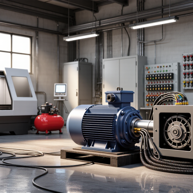
Choosing a Power Phase Converter is a practical engineering decision, not merely a voltage-selection exercise. It affects motor performance, equipment life, energy use, and production continuity. The U.S. Department of Energy reports that motor-driven systems consume a major share of industrial electricity, often estimated near 70% in manufacturing facilities. Small conversion losses can therefore become substantial operating costs.
The correct choice begins with the load. A three-phase machine may require stable voltage, balanced phases, and sufficient starting torque. A CNC machine, air compressor, and irrigation pump can respond very differently to the same converter. Rotary converters often suit varied industrial loads, while static converters may fit lighter-duty applications. Variable-frequency drives can provide speed control, but they require careful attention to harmonics, motor insulation, and compatibility.
Details matter.
The International Electrotechnical Commission’s IEC 60034 series provides widely recognized requirements for rotating electrical machines. NEMA MG 1 also offers guidance on motors, voltage variation, temperature rise, and operating conditions. These standards support a reliable evaluation, but they do not replace a site survey. Measure the incoming voltage, motor horsepower, starting current, duty cycle, and phase imbalance. Check the panel capacity and cable length, too.
A common mistake is choosing by horsepower alone. That shortcut can fail when several motors start together or when sensitive electronics share the supply. This guide explains how to compare converter types, calculate capacity, verify installation requirements, and evaluate long-term operating costs. The final answer may not be the cheapest unit. It should be the safest, most stable, and properly matched solution for the actual workplace.
How to Choose a Power Phase Converter?
A power phase converter changes single-phase electricity into usable three-phase power. Its design determines motor performance, efficiency, and starting behavior. A rotary converter uses a three-phase idler motor to generate the missing phases. It suits machine tools, pumps, and compressors with changing loads. A static converter uses capacitors for starting, but the motor usually produces reduced horsepower. It is simpler, though less flexible. Digital converters use electronic controls to create a more balanced output. They often provide better voltage regulation and monitoring.
The difference matters. IEA analysis estimates that electric motor-driven systems consume about 46% of global electricity. Small efficiency losses can therefore become expensive over time. When selecting a converter, check voltage, frequency, motor horsepower, starting current, and duty cycle. Do not size it from the nameplate horsepower alone. A compressor may demand several times its running current during startup. A rotary unit may need extra capacity for that surge. A digital unit may require careful programming and clean installation.
Field experience shows that load balance is frequently overlooked. Measure each phase under real operating conditions, preferably with the machine running. The U.S. Department of Energy’s motor-system guidance emphasizes correct sizing, voltage quality, and maintenance as major efficiency factors. However, published savings estimates are not guarantees. Cable length, ambient heat, and motor age can change results. A converter that works well on a lathe may perform poorly with a high-inertia pump. Review the manufacturer’s technical data and have a qualified electrician verify protection settings before energizing the equipment.
Choosing a phase converter starts with accurate load information, not guesswork. Record each machine’s voltage, frequency, phase, horsepower, and full-load amperage. Check the nameplate carefully. It may not show the real starting demand.
Measure actual current with a qualified electrician’s clamp meter. Capture readings while the motor starts, runs, and stops. Starting current can briefly reach several times the running current. That moment can trip a breaker or weaken voltage. It matters.
List every device that may operate at once. Include motors, pumps, compressors, heaters, controls, and lighting. Calculate the combined running load, then allow capacity for the largest starting motor. A converter sized only for average demand may struggle during sudden load changes.
I have seen apparently suitable installations fail because operators underestimated a compressor’s startup surge. The calculation looked correct. The operating pattern was not.
Confirm the available supply before selecting equipment. Verify service voltage, phase arrangement, frequency, breaker rating, conductor size, and grounding. The converter’s output must match the machine’s required voltage and phase. It should also tolerate the site’s duty cycle and expected imbalance. Leave practical headroom, but avoid extreme oversizing, which can increase cost and reduce efficiency. Static, rotary, and electronic designs behave differently under motor loads. Their suitability depends on starting current and load balance, not preference alone. Local electrical requirements still apply, and a licensed professional should verify the final installation.
Choosing a power phase converter requires more than matching voltage and horsepower. Capacity must handle starting current, not only the motor’s running load. A compressor may demand several times its rated current during startup. Undersizing can cause voltage sag, nuisance trips, and overheated windings. Leave practical headroom, but avoid excessive oversizing. It may increase idle losses and purchase cost.
Efficiency deserves equal attention. The U.S. Department of Energy’s Motor Systems Market Assessment reports that motor-driven systems use about 68% of electricity in U.S. manufacturing. Even small conversion losses can become expensive across long operating hours. Compare input power, output power, power factor, and no-load consumption. A converter showing high efficiency at one load may perform poorly at another. That detail is often missed.
Output quality protects sensitive equipment. Check voltage balance, frequency stability, waveform distortion, and transient response under changing loads. IEEE 519-2022 provides recommended limits for harmonic distortion in power systems, making it a useful reference during acceptance testing. Record readings with a true-RMS meter while the machine starts, runs, and stops. Field technicians sometimes focus only on the nameplate rating. I have seen that approach overlook unstable output. A quieter converter is not automatically a cleaner converter. Request measured data, test conditions, and efficiency curves before choosing.
Comparing converter capacity, efficiency, and output quality
This chart compares typical converter sizes from 5 to 30 kVA. Larger converters generally achieve higher efficiency and tighter voltage regulation, while voltage regulation values closer to 0% indicate better output quality. Actual performance depends on load balance, ambient conditions, wiring, and converter design.
Choosing a phase converter starts with the installation, not the nameplate. Check the incoming voltage, available amperage, grounding method, and panel capacity. Measure voltage during machine startup, because a quiet meter reading can hide a serious drop. The U.S. Department of Energy reports that industrial motor systems consume more than half of industrial electricity. Poor phase balance can therefore increase heat, losses, and maintenance costs. I have seen installations fail because the converter was sized for running current, not starting current. That mistake is easy to repeat.
Safety features deserve equal attention. Look for overload protection, short-circuit protection, thermal monitoring, and a clearly accessible disconnect. NFPA 70 requires suitable overcurrent protection and grounding practices for electrical equipment. IEC 60204-1 also emphasizes emergency stopping and protective bonding in machinery systems. Confirm that the enclosure suits the site. Dust, moisture, heat, and vibration can shorten service life quickly. Compatibility is more than matching voltage. Check motor horsepower, frequency, starting method, control transformers, variable-speed drives, and sensitive electronics. Some converters perform well with a basic motor but behave poorly with automated controls. A qualified electrician should verify phase sequence and load balance after installation. Record the readings. Recheck them after the machine reaches operating temperature. My own preference is conservative sizing, though it can increase upfront cost. Cutting that margin may look efficient, but it often leaves fewer options when production expands.
| Evaluation Dimension | What to Check | Typical Requirement or Technical Consideration | Why It Matters | Selection Guidance |
|---|---|---|---|---|
| Available Utility Supply | Incoming voltage, frequency, number of phases, and service capacity | Confirm whether the site has single-phase or three-phase service and verify the rated voltage and frequency shown on the electrical panel or utility documentation. | A converter cannot correct an unsuitable incoming service voltage or an undersized electrical supply. | Verify Before Purchase |
| Required Output | Output phase configuration, voltage, frequency, and usable current | The converter output must match the equipment nameplate. Voltage and frequency must remain within the equipment manufacturer's stated operating limits. | Incorrect output conditions can cause overheating, nuisance trips, poor motor performance, or equipment damage. | Match the Nameplate |
| Load Type | Motor, resistive heater, transformer, rectifier, welding equipment, or electronic load | Motor loads have starting current and may require more capacity than their continuous running current suggests. Electronic loads may require a converter with a controlled and balanced output. | Different loads place different demands on starting torque, voltage stability, waveform quality, and peak current. | Assess the Load Profile |
| Motor Starting Demand | Locked-rotor current, starting method, acceleration time, and frequency of starts | Direct-on-line motors can draw several times their rated full-load current during startup. A soft starter or variable-frequency drive may reduce starting stress when compatible. | An undersized converter may fail to start the motor, trip protection, or produce excessive voltage sag. | Size for Starting |
| Converter Technology | Rotary, static, or electronic/variable-frequency design | Rotary units can support motor loads with a generated phase. Static units are generally used for selected motor-starting applications and may not provide balanced three-phase power for all loads. Electronic units can provide controlled frequency and voltage when properly specified. | The operating principle determines load compatibility, output quality, maintenance needs, and control capability. | Choose by Application |
| Capacity Rating | Continuous output rating, overload capability, and motor horsepower or kilowatt requirement | Compare the converter's continuous rating with the largest connected load and consider simultaneous operation of all loads. Do not rely only on a motor's nominal horsepower. | Capacity based only on nominal motor size may be inadequate during startup or combined operation. | Include a Design Margin |
| Load Balance | Phase-to-phase voltage balance and current distribution | Three-phase motors generally perform best when phase voltages and currents are closely balanced. Measure the output under the actual operating load during commissioning. | Voltage imbalance can increase motor current and temperature and may shorten motor life. | Test Under Load |
| Overcurrent Protection | Branch-circuit breaker or fuse, short-circuit protection, and conductor ampacity | Protection must be selected according to local electrical codes, conductor size, equipment ratings, and the converter manufacturer's instructions. | Proper overcurrent protection limits damage from short circuits, overloads, and wiring faults. | Use Code-Compliant Protection |
| Grounding and Bonding | Equipment grounding conductor, enclosure bonding, and grounding electrode requirements | Connect and bond the converter and downstream equipment as required by the applicable electrical code. Never use a neutral conductor as a substitute for protective grounding. | A reliable grounding path helps protective devices operate during a fault and reduces shock risk. | Mandatory Safety Check |
| Safety Features | Overload, overtemperature, phase-loss, under-voltage, over-voltage, and emergency-stop functions | Choose protection appropriate to the converter design and connected equipment. Emergency-stop controls should remove hazardous energy in accordance with the machine safety design. | Protection features reduce the likelihood of equipment damage, fire, and unsafe restart conditions. | Prioritize Built-In Protection |
| Installation Environment | Indoor or outdoor location, ambient temperature, humidity, dust, water, vibration, and corrosive substances | Use an enclosure with an ingress-protection rating suitable for the location. Maintain the manufacturer's required ventilation clearance and avoid blocked air passages. | Heat, moisture, dust, and vibration can reduce reliability and cause premature component failure. | Match the Enclosure to the Site |
| Space and Ventilation | Mounting area, service clearance, airflow, and heat dissipation | Install the unit on a stable surface with sufficient clearance for cooling and maintenance. Do not place heat-sensitive equipment directly above a heat-generating converter. | Insufficient airflow can trigger thermal protection or reduce service life. | Allow Service Clearance |
| Compatibility with Controls | Contactors, relays, sensors, variable-frequency drives, programmable controllers, and control transformers | Check control-circuit voltage, switching method, grounding arrangement, electromagnetic compatibility, and whether the connected controls require a stable or isolated supply. | Power compatibility does not automatically guarantee control-system compatibility. | Review the Complete System |
| Sensitive Electronics | Controllers, computers, measurement systems, communication equipment, and adjustable-speed drives | Confirm waveform quality, voltage regulation, harmonic performance, and grounding requirements. A general-purpose phase converter may not be suitable for sensitive electronics. | Electrical noise, harmonics, or voltage variation can cause malfunction or communication errors. | Obtain Technical Approval |
| Noise and Vibration | Audible noise, mechanical vibration, mounting surface, and nearby work areas | Rotating equipment may produce more sound and vibration than electronic equipment. Use suitable mounting and isolation methods where required. | Noise and vibration can affect workers, precision machinery, and nearby instruments. | Consider the Work Environment |
| Maintenance Requirements | Bearing condition, cooling fan, terminals, filters, capacitors, and inspection intervals | Rotary equipment requires mechanical inspection, while electronic equipment may require cooling-system and connection checks. Follow a documented preventive-maintenance schedule. | Routine maintenance helps detect overheating, loose connections, wear, and contamination before failure. | Plan Long-Term Service |
| Installation and Commissioning | Qualified installer, torque checks, insulation condition, rotation direction, and load testing | Installation and testing should be performed by qualified electrical personnel. Verify phase sequence, output voltage, current, protective-device operation, and motor rotation before normal use. | Commissioning confirms that the installed system operates safely under real conditions. | Test Before Full Operation |
| Regulatory Requirements | Local electrical code, workplace safety rules, inspection requirements, and applicable product certifications | Requirements vary by jurisdiction and installation type. Confirm applicable rules with the authority having jurisdiction or a licensed electrical professional. | Compliance may be required for legal operation, insurance, inspections, and worker safety. | Check Local Regulations |
| Best-Fit Decision | Supply conditions, load characteristics, environment, safety, controls, and future expansion | Select a converter only after documenting the complete electrical load and installation conditions. Include reasonable capacity for expected future loads without exceeding the service rating. | A system-level decision is more reliable than choosing by price, horsepower, or physical size alone. | Use a Complete Specification |

Note: Electrical installation, protection, grounding, and commissioning should be reviewed and completed by qualified personnel in accordance with applicable local codes and equipment instructions.
How to Choose a Power Phase Converter?
Selecting a reliable phase converter starts with the equipment, not the converter label. Check the motor’s voltage, horsepower, starting current, and duty cycle. A machine that runs lightly may need less capacity than a compressor with heavy starts. Confirm the available utility supply and required output phase. Small voltage errors can create heat, vibration, and early motor wear. They are easy to miss.
Tips: Choose a converter with reserve capacity. Ask for measured output performance, not only advertised ratings. Check enclosure protection, cooling, overload protection, and service access. Review the installation manual with a qualified electrician. Test the system while the machine is under its normal load. Record voltage readings during startup and operation.
Long-term performance depends on balance and maintenance. A converter should deliver stable phase voltage across changing loads. Poor balance may cause nuisance trips or shorten winding life. Keep vents clean and inspect terminals for looseness. Dust builds quietly. Heat does too. I have found that a perfect calculation can still disappoint when several machines start together. Recheck the load schedule before purchase. Consider future equipment, seasonal temperature changes, and available technical support. Parts availability also matters. A reliable converter is not simply powerful; it is properly matched, monitored, and maintainable.
880 W 9th Street
Upland, California 91786
884 W 9th Street
Upland, California 91786
886 W 9th Street
Upland, California 91786
884 W 9th Street
Upland, California 91786